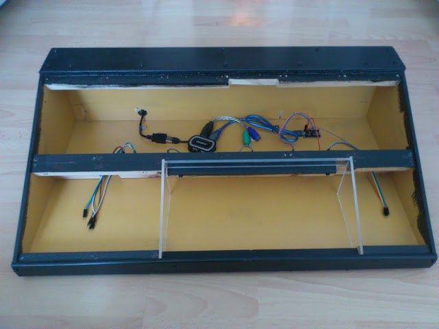
The encasing is a 6 mm plywood box with ~15 mm wood lists that I screw the modules to. It was a bit tight to frame the keyboard with plywood so i had to use 4 mm acrylic glass there instead. In the back I mounted a USB hub and a PS2 to USB converter for the keyboard. The "main" computer is a small Arduino Pro Micro located to the right of the blue USB cable that connects it to the USB hub.
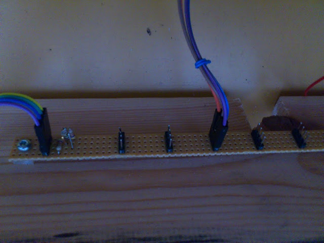
The backplane bus is the heard of the whole console. It distributes 5 volt power and the I2C communication bus to all modules mounted in the encasing. I've used two strips of veroboard with long copper strips to build it and it consist only of a bunch of connector pins and two 4.7 kohm pull up resistors for the bus. I also added a totally meaningless red miniature LED that indicates when the power strips are correctly connected and powered.
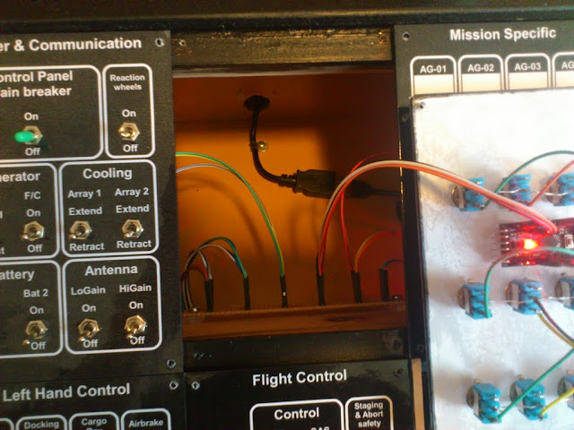
A closer look at the "mainframe" and the networking fabric.

It also shows the connection to the bus extension to the left.

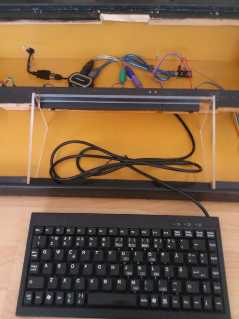
There is plenty of room for the long keyboard cable under the keyboard. The keyboard isn't attached in any way into the box other than by a very snug fit. I actually have to remove parts of the panels to get at good grip to yank it out agan once it's in place.

The enclosure takes 9 modules (size 100x150 mm). All modules can (or should be) placed anywhere. There is an exception as the display module is the only module that follows the original design spec to the limit. My specs was that there would be at least 10 mm clearance from all edges of the module front. The wooden lists I use was 15 mm and it worked well for all other modules as they had a little extra margin, but the display module did not. That is the reason I had to remove some of the wood where the display module is to be mounted.
Finally a little peek into the box when all modules are connected. I shot this just before popping the last one in place.
EDIT: Here's a couple of pictures of the whole thing assembled and labeled.


No comments:
Post a Comment